TILIA – Dual Reactor System with Internal Redundancy
TILIA is a Burn-Wet System for advanced Etch and CVD applications in the semiconductor industry.
Waste Gas Treatment – TILIA
Disposal of pyrophoric, fluorinated, toxic or long-lived environmentally harmful gases and reaction products
TILIA is a system for the disposal of pyrophoric, fluorinated, toxic or long-lived environmentally harmful gases and reaction products which are used in chemical and physical processes in the semiconductor and solar industry or are generated by the process. Disposal takes place via combustion and subsequent scrubbing of particles, as well as absorption of soluble gas components with the aid of a scrubbing liquid.
TILIA DUO
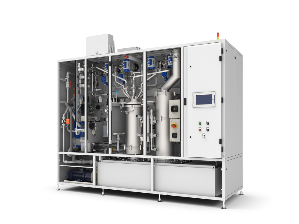
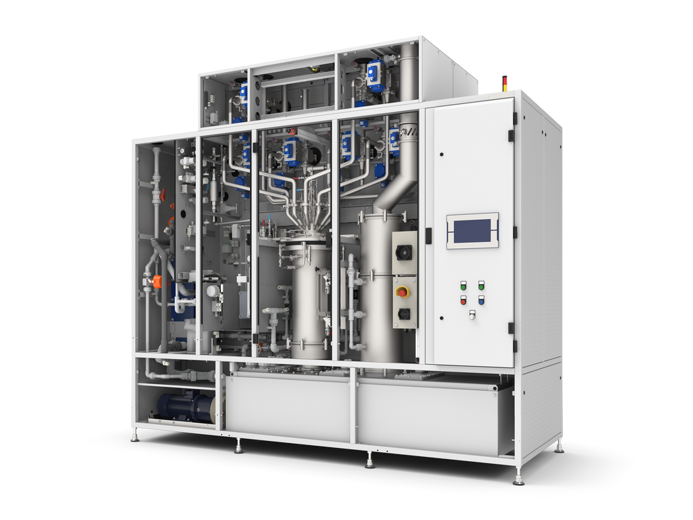
TILIA DUO is a dual reactor system with internal redundancy. It contains two independent TILIA units, each consisting of a combination of one combustion chamber and one scrubber with an integrated demister located above it. There is one power distribution box per side. In the maximum configuration, each unit has six inlets for waste gas as well as six other inlets which are connected to the respective other TILIA unit via back-up lines. If necessary, the waste gas at the inlets of one of the two units can be diverted to the other unit. As a result, the system has internal redundancy and thus very high availability.
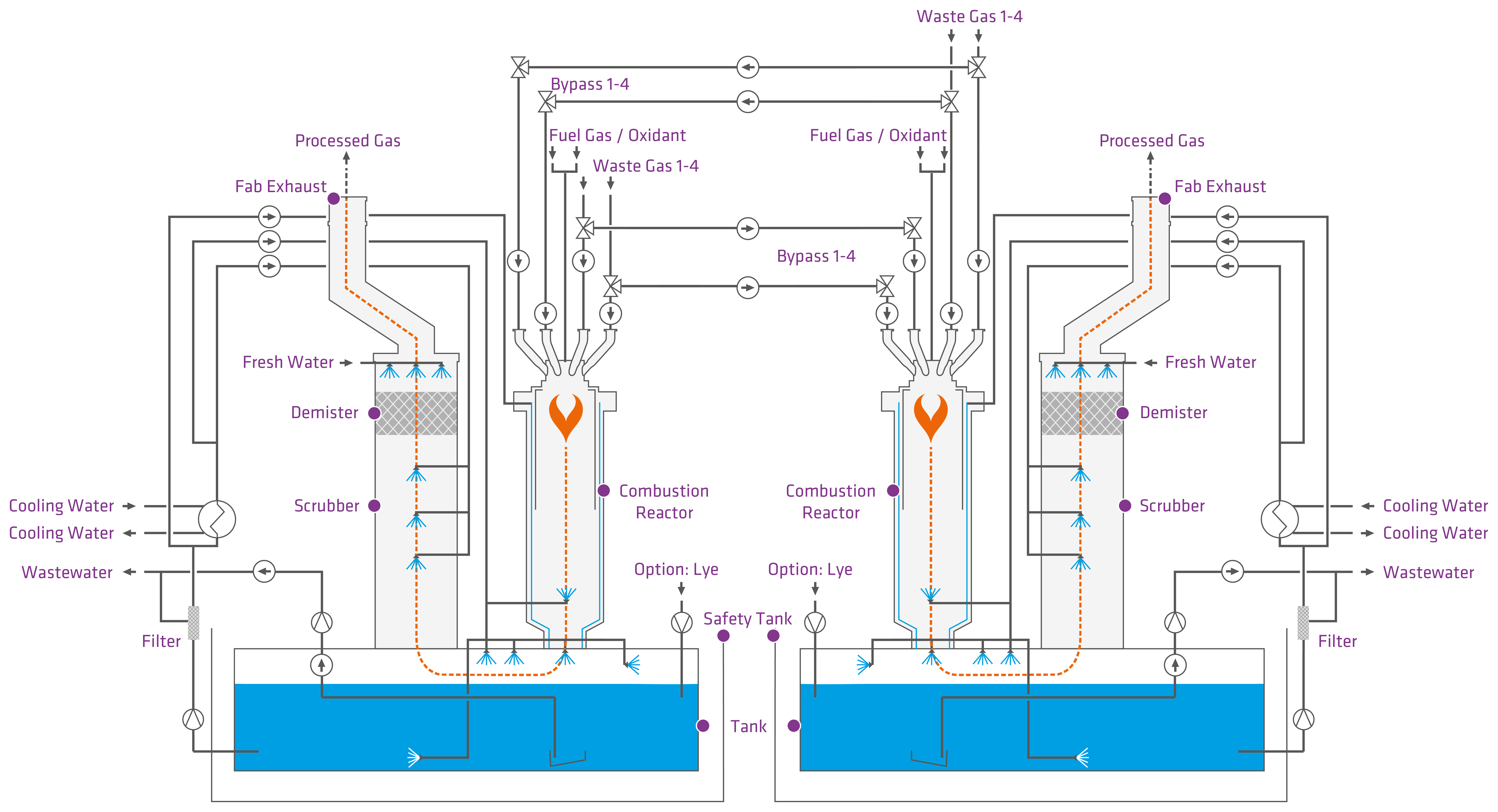
Functioning principle of the TILIA DUO with 4+4 inlets per reactor
Combustion Reactor
The waste gas is fed into the combustion reactor and burned there with the help of fuel gas and an oxidising agent. The burner is usually operated with a mixture of fuel gases (propane, natural gas) and oxygen or compressed dry air. Due to its design, the waste gas flows through the combustion reactor from top to bottom. The flame energy causes the chemical bonds to break apart. The decomposition products oxidise in the flame and form chemically stable compounds.
Quench Zone
A quench zone is added for faster cooling of the gas after discharge from the combustion reactor. Here the gas is cooled down significantly in order to avoid recombination of the combustion products and to reduce the temperature of the exhaust gas before the following process step.
Scrubber
The combusted waste gas flows through the scrubber according to the counter flow principle. There are several spray nozzles and a demister in the scrubber. Scrubbing liquid is sprayed into the gas stream with the spray nozzles. During washing, particles are suspended in the scrubbing liquid and acidic components are neutralised by a basic scrubbing liquid.
Demister
In the demister, the water droplets are separated on the surface of the filling materials. The separated water enters the scrubbing liquid tank.
Scrubbing Liquid Tank and Recirculation loop
A scrubbing liquid tank is located below the burner and scrubber and serves as a collection tank for the scrubbing liquid. The liquid used is water, to which lye can be added, depending on the design. The scrubbing liquid is circulated in a recirculation loop and has many functions here. It absorbs soluble gas components in the scrubber and cools the system.
TILIA — for advanced Etch and CVD applications
Application
- CVD / Etch (Metal, Poly, Oxides, …) / Epitaxy / GaN / MOCVD / LED, …
Goals
- To meet the need of increasing process gas flows
Higher wafer throughput per abatement footprint
→ One TILIA replaces several previous abatement systems. - To meet the increasing complexity of Etch and CVD mainframes
→ Combination of CVD and Etch chambers
Basic Features
- Burn-/Wet System (Scrubber) with liquid recirculation
- Serves up to 8 or 12 process chambers with
- Up to 2400 slm total flow
- Best in class capacity per footprint
- With cost effective integrated backup
- Reactor capacity up to 1200 slm inert gas (per reactor)
- Implementation of safety requirements of new processes with
- Higher number of process modules
- Larger process gas flows
- Higher total flows

TILIA 4+4

TILIA 6+6
Technical Data
| TILIA DUO 4+4 | TILIA DUO 6+6 | |
|---|---|---|
| Pump down capacity: | 3000 slm (8 inlets) | 3000 slm (12 inlets) |
| Burner power (tunable): | 2 x 100 kW | 2 x 100 kW |
| Inlets: | 8 x DN40 with internal redundancy | 12 x DN40 with internal redundancy |
| Uptime: | > 99.9% | > 99.9% |

Consulting and Technology Selection
The selection of the appropriate technology is carried out by our application specialists after analyzing the situation on site. Information about the process tool, vacuum pump, gas types and flows as well as the available operating materials are decisive.
In order to ensure a long-term runtime and tool availability, our service and technical support are available on demand or on-site as soon as the system is commissioned.
Dr. Christian Kuhne
Director Sales Global
