TILIA – Doppelreaktorsystem mit interner Redundanz
TILIA ist ein Brenner-Wäscher System für fortschrittliche Ätz- und CVD-Anwendungen in der Halbleiterindustrie.
Abgasreinigung – TILIA
Entsorgung von pyrophoren, fluorierten, giftigen oder langlebigen umweltschädlichen Gasen und Reaktionsprodukten
TILIA ist ein System zur Entsorgung von pyrophoren, fluorierten, toxischen oder langlebigen umweltschädlichen Gasen und Reaktionsprodukten, die in chemischen und physikalischen Prozessen in der Halbleiter- und Solarindustrie eingesetzt werden oder durch den Prozess entstehen. Die Entsorgung erfolgt durch Verbrennung und anschließende Partikelwäsche sowie Absorption der löslichen Gasbestandteile mit Hilfe einer Waschflüssigkeit.
TILIA DUO
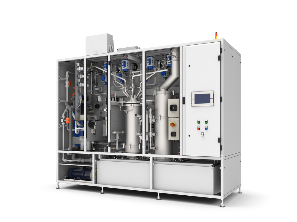
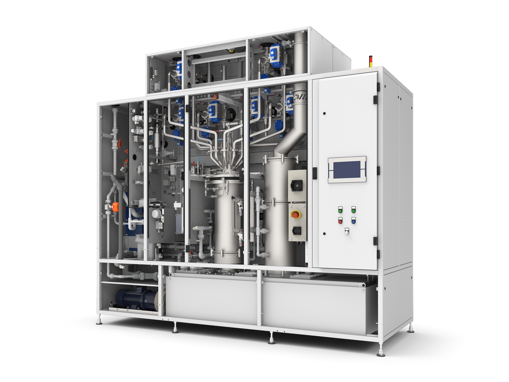
TILIA DUO ist ein Doppelreaktorsystem mit interner Redundanz. Es enthält zwei unabhängige TILIA-Einheiten, die jeweils aus einer Kombination aus einer Brennkammer und einem Wäscher mit einem darüber befindlichen integrierten Demister bestehen. Pro Seite gibt es einen Stromverteilerkasten. Im Maximalausbau verfügt jede Einheit über sechs Abgaseinlässe sowie sechs weitere Einlässe, die über Back-up-Leitungen mit der jeweils anderen TILIA-Einheit verbunden sind. Bei Bedarf kann das Abgas an den Eingängen einer der beiden Einheiten in die andere Einheit umgeleitet werden. Das System ist somit intern redundant und hat eine sehr hohe Verfügbarkeit..
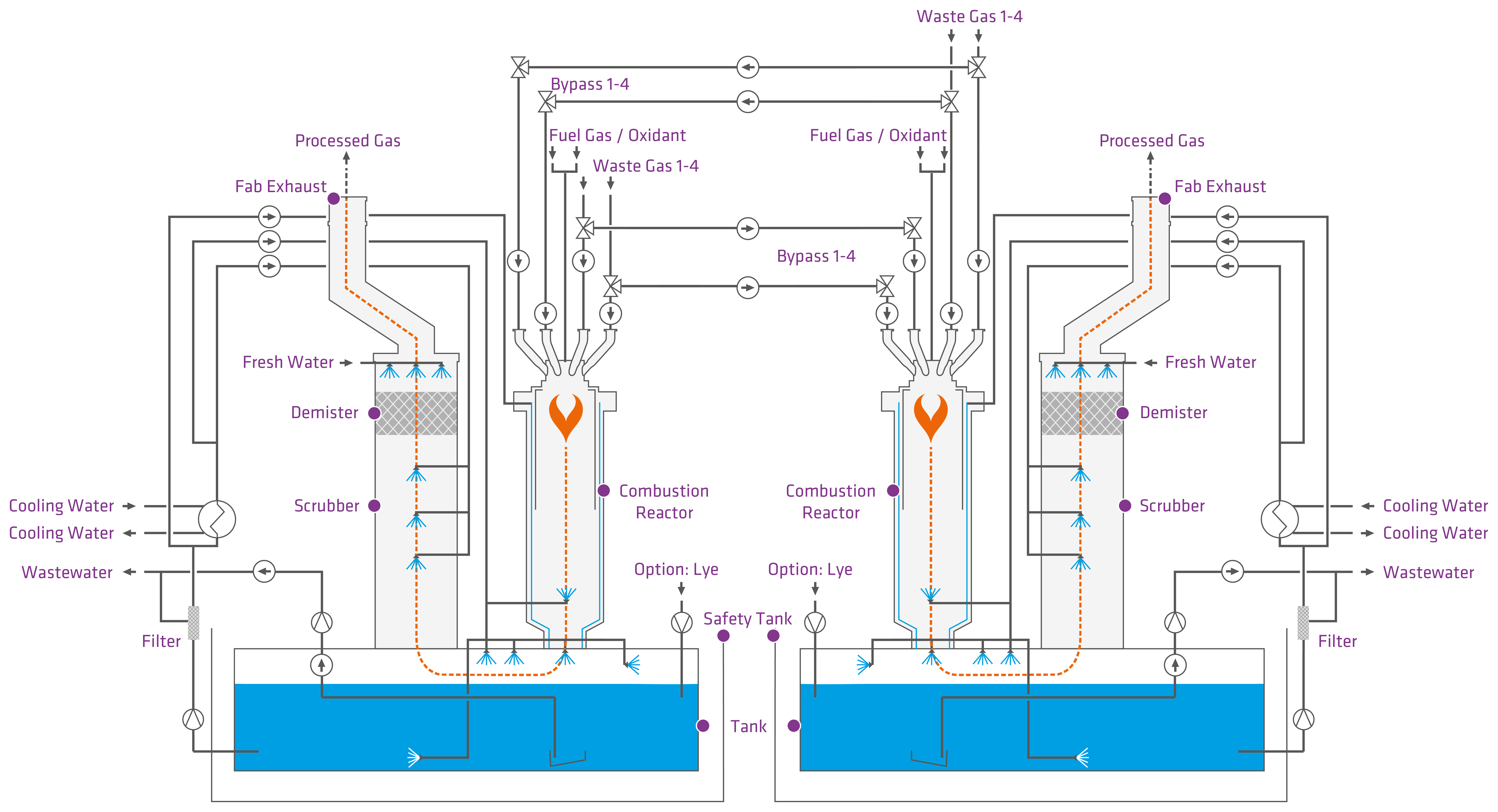
Funktionsprinzip der TILIA DUO mit 4+4 Einlässen pro Reaktor
Verbrennungsreaktor
Das Abgas wird in den Verbrennungsreaktor geleitet und dort mit Hilfe von Brenngas und einem Oxidationsmittel verbrannt. Der Brenner wird in der Regel mit einem Gemisch aus Brenngasen (Propan, Erdgas) und Sauerstoff oder komprimierter Trockenluft betrieben. Konstruktionsbedingt strömt das Abgas von oben nach unten durch den Verbrennungsreaktor. Die Flammenenergie bewirkt, dass die chemischen Bindungen aufgebrochen werden. Die Zersetzungsprodukte oxidieren in der Flamme und bilden chemisch stabile Verbindungen.
Quench Zone
Zur schnelleren Abkühlung des Gases nach dem Austritt aus dem Verbrennungsreaktor wird eine Quench Zone hinzugefügt. Hier wird das Gas stark abgekühlt, um eine Rekombination der Verbrennungsprodukte zu vermeiden und die Temperatur des Abgases vor dem folgenden Prozessschritt zu senken.
Wäscher
Das verbrannte Abgas durchströmt den Wäscher nach dem Gegenstromprinzip. Im Wäscher befinden sich mehrere Sprühdüsen und ein Demister. Mit den Sprühdüsen wird Waschflüssigkeit in den Gasstrom gesprüht. Bei der Wäsche werden die Partikel in der Waschflüssigkeit suspendiert und die sauren Bestandteile durch eine basische Waschflüssigkeit neutralisiert.
Demister
Im Demister werden die Wassertröpfchen an der Oberfläche der Füllmaterialien abgeschieden. Das abgeschiedene Wasser gelangt in den Waschflüssigkeitsbehälter.
Waschflüssigkeitstank und Rezirkulationskreislauf
Ein Waschflüssigkeitsbehälter befindet sich unter dem Brenner und dem Wäscher und dient als Sammelbehälter für die Waschflüssigkeit. Die verwendete Flüssigkeit ist Wasser, dem je nach Ausführung Lauge zugesetzt werden kann. Die Waschflüssigkeit wird in einem Rezirkulationskreislauf umgewälzt und hat dabei mehrere Funktionen. Sie absorbiert lösliche Gasbestandteile im Wäscher und kühlt das System.
TILIA – for advanced Etch and CVD applications
Anwendung
- CVD / Ätzen (Metall, Poly, Oxides, …) / Epitaxy / GaN / MOCVD / LED, …
Ziele
- Um den Bedarf an steigenden Prozessgasströmen zu decken
Höherer Wafer-Durchsatz pro Reinigungs-Footprint
→ Eine TILIA ersetzt mehrere frühere Abluftreinigungssysteme. - Um der zunehmenden Komplexität von Ätz- und CVD-Mainframes gerecht zu werden
→ Kombination von CVD- und Ätzkammern
Spezifikationen
- Brenner-Wäscher System (Scrubber) mit Flüssigkeitsrückführung
- Bedient bis zu 8 oder 12 Prozesskammern mit
- Bis zu 2400 slm Gesamtdurchfluss
- Beste Kapazität pro Stellfläche
- Mit kosteneffektivem integriertem Backup
- Reaktorkapazität bis zu 1200 slm Edelgas (pro Reaktor)
- Umsetzung der Sicherheitsanforderungen von neuen Prozessen mit
- Höhere Anzahl von Prozessmodulen
- Größere Prozessgasströme
- Höhere Gesamtdurchflüsse

TILIA 4+4

TILIA 6+6
Technische Daten
| TILIA DUO 4+4 | TILIA DUO 6+6 | |
|---|---|---|
| Abpumpleistung: | 3000 slm (8 Einlässe) | 3000 slm (12 Einlässe) |
| Brennerleistung (einstellbar): | 2 x 100 kW | 2 x 100 kW |
| Einlässe: | 8 x DN40 mit interner Redundanz | 12 x DN40 mit interner Redundanz |
| Standzeit: | > 99.9% | > 99.9% |

Beratung und Technologieauswahl
Die Auswahl der geeigneten Technologie erfolgt durch unsere Anwendungsspezialisten nach Analyse der Situation vor Ort. Dabei sind Informationen über das Prozesswerkzeug, die Vakuumpumpe, die Gasarten und ‑ströme sowie die verfügbaren Betriebsmittel entscheidend.
Um eine langfristige Laufzeit und Werkzeugverfügbarkeit zu gewährleisten, stehen unser Service und technischer Support auf Abruf oder vor Ort zur Verfügung, sobald die Anlage in Betrieb genommen wurde.
Dr. Christian Kuhne
Director Sales Global
